Dropped Noise Floor At Carrier Frequency

Transmit Signal Leakage In Lte Frequency Division Duplexing Applications Nutaq Nutaq

Edn 8 Ways To Clarify Spurious Emissions

Noise Floor Where Do We Go From Here

Dros Drop Phase Noise Microwaves Rf
Https Ieeexplore Ieee Org Iel7 7260 4357983 07987033 Pdf

Awr Visual System Simulator Modeling Guide Chapter 3 Noise Modeling In Vss
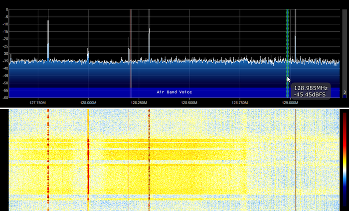
For the signal to be detected it must be higher than the noise floor 6.
Dropped noise floor at carrier frequency. In signal theory the noise floor is the measure of the signal created from the sum of all the noise sources and unwanted signals within a measurement system where noise is defined as any signal other than the one being monitored. At this point we would like to know the noise floor in our receiver i e. The noise floor can be defined as the measure of the signal created from the sum of all the noise sources and unwanted signals within a system. The voltage adds to the.
Building a completely noise. Place the spectrum analyzer in video averaging mode and get the noise floor average across frequency or danl in db. The carrier to noise ratio is defined as the ratio of the received modulated carrier signal power c to the received noise power n after the receiver filters. Letter 1 represents frequency for carrier related measures.
Knowing the spectrum analyzer danl and looking at the noise source with noise on if we can see the jump in noise floor. High frequency noise while computers and other electronic equipment generate noise in all frequency ranges. For this reason the term minimum discernable signal mds is often used interchangeably with noise floor. Residual noise forms the noise floor.
In radio communication and electronics this may include thermal noise black body cosmic noise as well as atmospheric noise from distant thunderstorms and. The system designer usually specifies a carrier to noise ratio. This is related to the spectrum analyzer s noise figure and is a measure of the sensitivity of the analyzer. The level of the noise floor determines the lowest strength signals that can be received and therefore the noise floor level is an important characteristic of any radio.
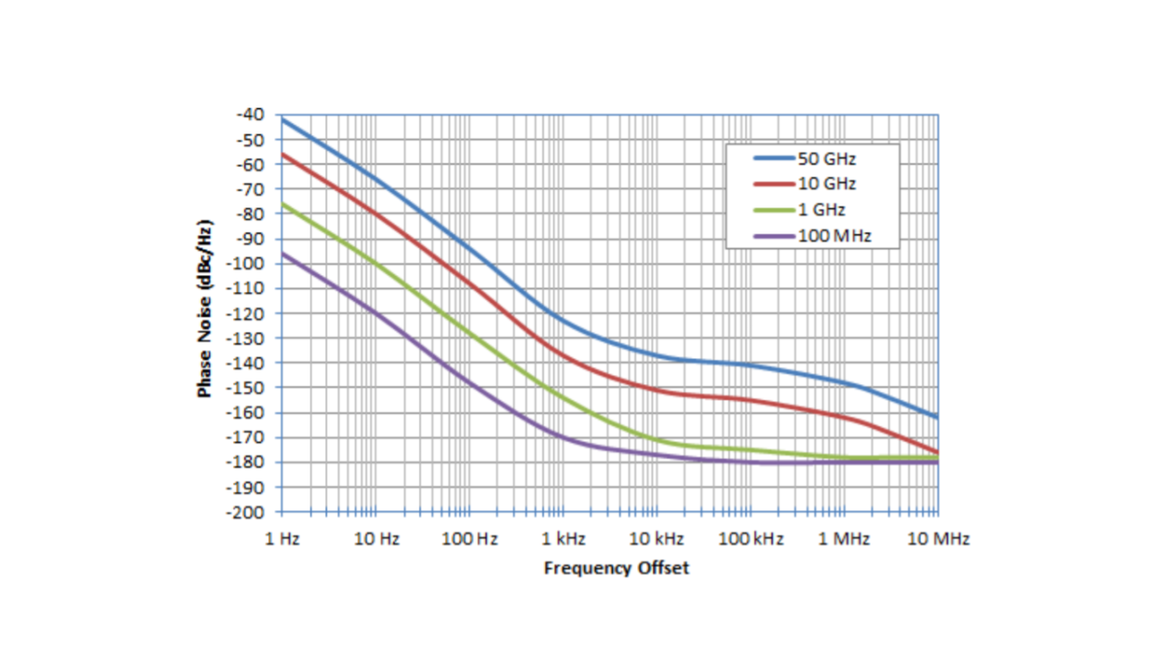
A reduction of 9 11 db in the noise floor level is realized between the city and rural environments over the 300 khz to 100mhz band. The noise power in the receiver intermediate frequency if filter bandwidth that comes from ktb. This data clearly shows that the medium frequency am band is significantly more affected by the noise floor than the vhf uhf or mobile cellphone service bands. If the carrier is considered as dc the frequencies measured with respect to the carrier are referred to as baseband offset from the carrier modulation noise or fourier frequencies.
When both carrier and noise are measured across the same impedance this ratio can equivalently be given as. Modulation related frequencies are designated f. However some references take the mds to be 3 or more db higher than the receiver noise floor.

Noise Power An Overview Sciencedirect Topics

Resolution Bandwidth An Overview Sciencedirect Topics

Agilent Technologies 8 Hints For Spectrum Analysis
Bats Distress Vocalizations Carry Fast Amplitude Modulations That Could Represent An Acoustic Correlate Of Roughness Scientific Reports

Why A Spectrum Analyzer Nimble This

Pwm Distortion Analysis Open Music Labs

Digital Problems Practical Solutions

Edn Phase Noise And The Y Factor Noise Figure
A 1 Mhz To 50 Ghz Direct Down Conversion Phase Noise Analyzer With Cross Correlation Rohde Schwarz

Analyzing And Managing The Impact Of Supply Noise And Clock Jitter On High Speed Dac Phase Noise Industry Articles

Noise Reduction Audacity Manual

Assess Quadrature Demodulator Noise Figure Using Vector Signal Analysis Microwaves Rf
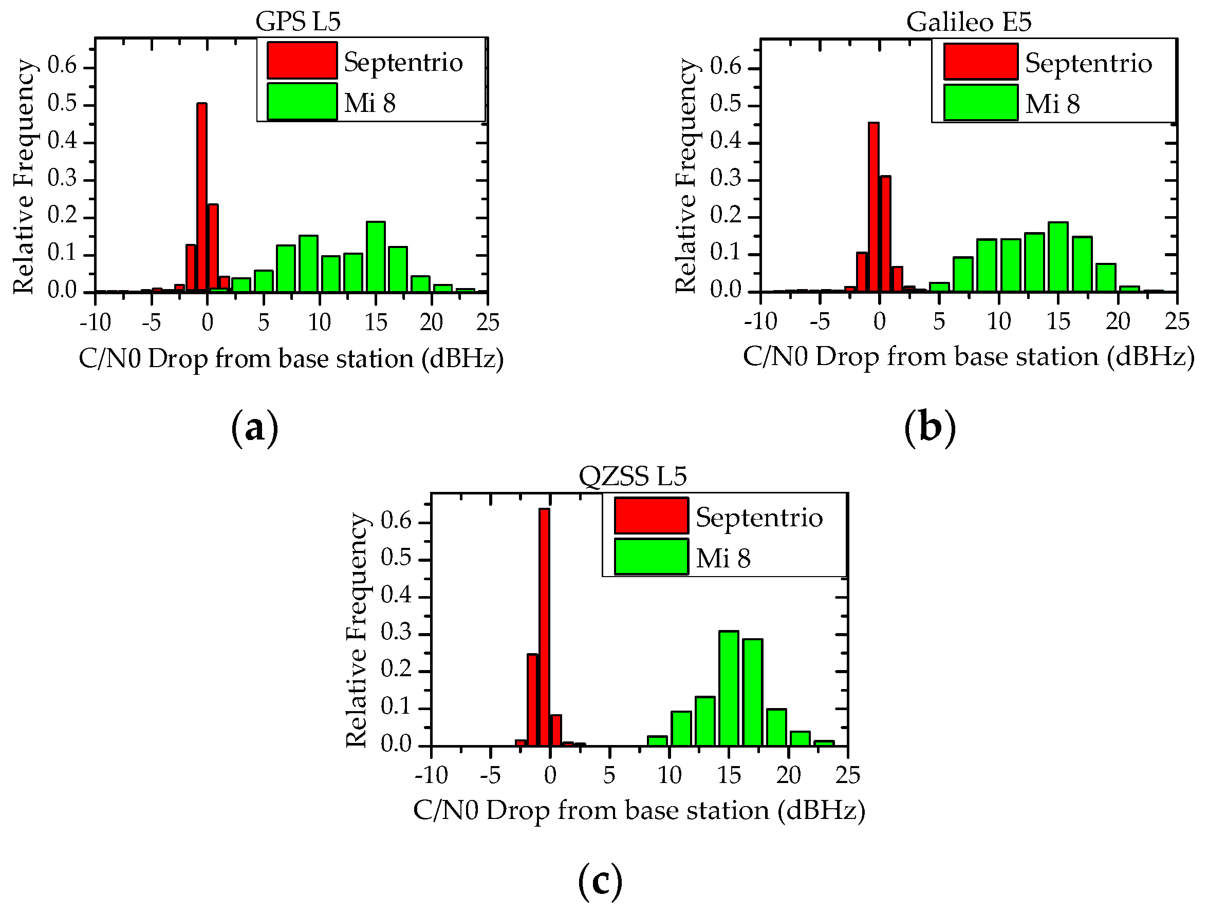
Remote Sensing Free Full Text Characteristics Analysis Of Raw Multi Gnss Measurement From Xiaomi Mi 8 And Positioning Performance Improvement With L5 E5 Frequency In An Urban Environment Html